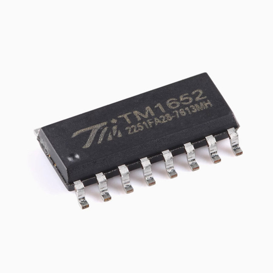
TM1652 SOP-16 LED Driver Control IC
Inhouse product
-
 ৳320.00
Reviews & Ratings
The TM1652 is a versatile LED driver control IC designed for driving LEDs, digital tubes, and dot matrix displays. It is commonly used in applications like electronic displays, control panels, and consumer electronics. Below is an overview of its features, pin configuration, and typical usage.
TM1652 Overview
Package: SOP-16 (Small Outline Package, 16 pins)
Function: LED driver with key scanning
Applications: LED displays, digital tubes, dot matrix screens, and control panels
Communication Interface: I2C (2-wire serial interface)
Output Channels: 8 segments x 4 digits (supports multiplexing)
Key Scanning: Supports up to 8x4 matrix key scanning
Brightness Control: Adjustable via PWM (Pulse Width Modulation)
Power Supply: 3.0V to 5.5V
Key Features
LED Driving:
Supports common cathode LED displays.
Can drive 8 segments x 4 digits (32 LEDs).
Brightness control for each segment.
Key Scanning:
Built-in 8x4 matrix key scanning.
Supports key press detection and debounce.
Communication:
I2C interface for easy integration with microcontrollers.
Address selection via pins (supports multiple devices on the same bus).
Low Power Consumption:
Designed for energy-efficient applications.
Flexible Configuration:
Adjustable display brightness.
Configurable display modes (e.g., 7-segment, 8-segment).
Pin Configuration (SOP-16)
| Pin No. | Pin Name | Description |
|---|---|---|
| 1 | SEG1 | Segment 1 output for LED display |
| 2 | SEG2 | Segment 2 output for LED display |
| 3 | SEG3 | Segment 3 output for LED display |
| 4 | SEG4 | Segment 4 output for LED display |
| 5 | SEG5 | Segment 5 output for LED display |
| 6 | SEG6 | Segment 6 output for LED display |
| 7 | SEG7 | Segment 7 output for LED display |
| 8 | SEG8 | Segment 8 output for LED display |
| 9 | GND | Ground (0V) |
| 10 | DIG1 | Digit 1 output for LED display |
| 11 | DIG2 | Digit 2 output for LED display |
| 12 | DIG3 | Digit 3 output for LED display |
| 13 | DIG4 | Digit 4 output for LED display |
| 14 | SDA | I2C Data line |
| 15 | SCL | I2C Clock line |
| 16 | VDD | Power supply (3.0V to 5.5V) |
Typical Application Circuit
LED Display Connection:
Connect the SEG1-SEG8 pins to the segments of the LED display.
Connect the DIG1-DIG4 pins to the common cathodes of the digits.
I2C Interface:
Connect SDA and SCL to the microcontroller's I2C pins.
Use pull-up resistors (typically 4.7kΩ) on both SDA and SCL lines.
Power Supply:
Connect VDD to a 3.0V to 5.5V power source.
Connect GND to the ground.
Key Scanning:
Connect the key matrix rows and columns to the appropriate pins (if key scanning is required).
Applications
Digital clocks and timers
Electronic scoreboards
Industrial control panels
Home appliances (e.g., microwave, washing machine displays)
Frequently Bought Products
Product Queries (0)
Login Or Registerto submit your questions to seller
Other Questions
No none asked to seller yet
-
৳320.00